Technical Desktops


9810A

Early Calc and Computers Selection:
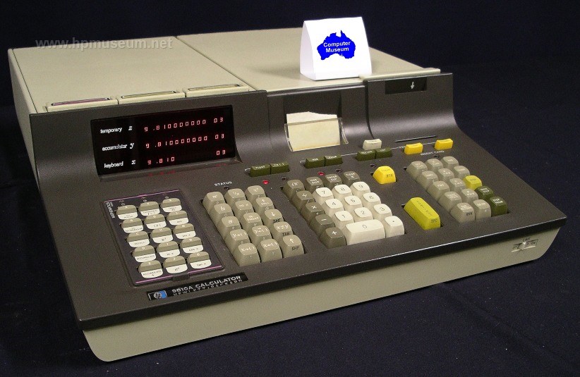
Name: 9810A
Product Number: 9810A
Introduced: 1971
Division: Calculator Products
Price: $2975
Catalogue Reference: 1972, page 408

Description:

The 9810A was HP's second generation RPN calculator. It replaced the 9100. Instead of a CRT, the 9810A had a three-line LED display. It was also upgradable with ROM modules to perform additional functions (math functions, peripheral I/O, etc). The 9810A had a built-in card reader and an optional 16-character, internal thermal printer. Unlike the 9100 which had a single expansion slot, the 9810A had four expansion slots in the rear of the machine.

To download an emulator of HP 9800 Series computers (9810, 9820 and 9830), visit Achim Burger's site at: http://sourceforge.net/projects/hp9800e.

Collector’s Notes:

The museum has one fully functioning 9810 and one partially functioning unit. The most common failure mode for these machines is no display on power up. This is usually caused by a failure on one of the pluggable PCBs inside the machine. If you have a functioning unit, you can determine which of the internal boards is bad by board swapping. Some of the PCBs in the 9810 are also common to the 9820 and the 9830. So, these computers are a source for swapping some of the boards in the 9810.

Almost all original 9810 and 9820 computers have defective magnetic card readers. The soft drive wheels on these assemblies become gooey over time and will not properly grip the cards. Click here for instructions on how to fix the drive wheels.


Tony Duell's Notes on the 9810 Printer:

The printhead has 80 resistive heating elements (16 characters, 5 pixels/character). They are not evenly spaced (in groups of 5, for each character), so graphics would be impossible, even if you could write machine code. There are 88 external connections, one for one end of each element (80 connections) and 8 common wires (for 10 elements each).

There are 2 PCBs on the printer. The 'interface' board (-66551) on the side and the 'driver' board (-66552) on the bottom.

The driver PCB contains:

The printhead flexiprint: This is integral with the PCB (which consists of glassfibre boards laminated onto the outside of the flexiprint). The printhead is clamped to the 'free' end of the flexiprint.

80 diodes turn the printhead elements into a 20*4 matrix with no sneak paths. Adjacent common connections from the printhead are connected together.

4 big transistors (Q1 to Q4) to ground the selected common lead and enable one bank of 20 elements at a time: These are driven by transistors from a '145 decoder chip (which gets its inputs from the interface board, and ultimately from the I/O interface shift register (in the main CPU). Note that the LSB input to this decoder is inverted so outputs 0,1 and 2,3 are swapped round in pairs. The other inputs are normal (the C and D inputs are essentially enables).

The motor driver circuit: The motor is a 2-phase AC motor (the windings are centre-tapped, but the taps are not used). The windings are driven by a pair of full-H drivers (that's the 8 transistors in a row across the board). Those in turn are driven by the '107 flip-flops and the '06 buffers. There are 2 inputs to the motor drive circuit, clock (to the ff's) and enable (to 4 of the buffer sections, which allow the rest of the drivers to work when the outputs are floating).

The interface board contains:

A 10 bit shift register (2 off '96). This extends the I/O register in the CPU (it takes the bits that fall off the end!) making a 26 bit register. 20 of the bits are the column drive signals to the printhead. The others are either not used, or used to select the printhead block to he used.

The 20 transistors (Q1 -- Q20, all 2N2907s) are the printhead column drivers. HP has been friendly -- Q1 drives column 1, etc. They are driven by '06 and '07 buffers as appropriate (the internal S/R is loaded with inverted data!).

Below those are 2 more transistors, Q23 and Q24. These are the buffers for the 2 switches on the mechanism (the microswitch at the front that detects when the manual feed lever is pressed, and the paper out contact). The switches return to +24V. These transistors (and associated resistors) buffer them to TTL levels.

At the top front are 2 more transistors (Q21, Q22). These are an astable multivibrator to give a motor clock signal for manual paper feed. When printing, the clock comes from the CPU as you might expect.

The remaining chips (gates and monostables) generate the motor clock pulse, the printhead enables pulse and the printer flag signal (back to the I/O interface).

Now for how to take it apart. It's not hard, but there are a lot of bits...

Remove the 3 screws and pull off the interface board (carefully, there's an edge connector connecting it to the driver board. Hold the driver board in position while doing this.

Unscrew the printhead pressure spring housing at the front (5/16" spanner). Remove the housing (basically a special bolt) and the spring). Undo the 2 screws holding the microswitch bracket to the side frames (left side has the washer and cable P-clip). Ease the bracket out; leave it hanging on the microswitch wires.

Remove the 2 self-locking nuts, compression springs, adjusting cams and screws that hold the printhead support levers to the side frames. When reassembling, you will have to adjust the cams for clear printing at each side.

Swing the complete printhead assembly forwards and down. Unplug the edge connector at the back of the driver board (carries the motor and switch wires), remove the driver board complete with the printhead.

If necessary, pull off the printhead support levers from the printhead clamp block (little nylon studs, just pressed in). Undo the 2 setscrews in the support block (1/16" Allen key), remove the printhead, flexiprint and clamp bar (rubber side towards the flexiprint). When reassembling, line up the flexiprint tracks with those on the printhead. Note that the levers fit with the flat surface towards the rear of the printer.

Now back to the main chassis. Remove the circlip on the gear on the left hand side (on the platten spindle). Pull off the gear. Loosen (do not remove) the motor mouting screws, slide the motor forwards to release the belt tension. Remove the front belt sprocket (note, it is supposed to rotate freely on its spindle!) and the belt. At this point it is possible to remove the motor if you don't want to dismantle the rest of the unit, but getting the nuts and washers back in is somewhat tricky.

On the other side, remove both circlips and gears. The larger gear fits on the upper (platten) spindle.

Remove the circlip from one end of the rear paper belt spindle (at the centre bottom). Slide out the spindle, recover the (black plastic) belt rollers.

Remove the smaller circlip from one end of the next spindle (going forwards). It carries 2 more small belt rollers and the out-of-paper contact. Remove the spindle, recover the rollers and leave the contact hanging on the wire.

Undo the 4 screws holding the platten bearing plates to the main side frames. Remove the plastic spacer strips (note how they are fitted). Rotate the manual feed lever though half a turn (this will take a little force to get it to go past the platten so that the LHS of this part will clear the hole in the bearing plate. Carefully separate the plates and remove the idler roller, belt drive roller and belts, platten, paper guide flap and manual feed lever.

Remove the rear 2 through-bolts from the printer side frames. This will free the rear part of the paper housing. Move it down to allow the paper guide wire to be unclipped and removed, then remove the housing section.

Remove the front 2 through-bolts, noting that the top one carries the tapped spacer that takes the interface PCB mounting screw. Separate the side plates, remove the front section of the paper housing. Leave the fixed part of the paper-out contact hanging on its wire.

Undo the 4 nuts and bolts and remove the motor. There's a spring washer under each nut and a flat washer under the bolt head.

Motor: Once the motor has been removed, it can be (partially) dismantled by first removing the 3 screws on the rear end cap. Then remove the cap and the 3 plastic sleeves on the tapped posts inside. Loosen both setscrews on the sprocket (1/16" Allen key again), remove the sprocket and the plastic collar under it. Remove the circlip then exposed, slide out the rotor. There are shims on both sides of the bearing -- make sure you recover all of them and keep them together. In fact fit the rear shim set back on the rotor shaft. The shaft runs in needle roller bearings, which can now be cleaned and greased (or replaced?).


Tony Duell's Notes on Card Reader Repair:

Take off the drive belt from the LHS. Then undo the 2 screws and remove the head. This is not essential, but you'd feel a right idiot if you damaged the head in subsequent work.

Remove the top left and bottom left card sensor bulb holders from the plastic frame, leave them hanging on the wires. Remove the screws from the pillars connecting the 2 side plates. The front bottom one on the right hand side, all the others on the left.

Separate the plates, and slide the 2 left hand card sensor photodetectors out of the plastic frame also. Continue separating the frames and remove the pinch roller/pressure pad assembly.

Remove lower front screw on the left side; remove the pillar and card guide. Remove the rear cover from the motor (2 tiny screws, you need a nut driver a few sizes smaller than most people have!).

Undo the 2 screws holding the wires to the brush gear. At this point the 2 plates can be completely separated, set the right hand one (with the cableform, etc) aside.

Remove the motor brushes (one more screw each) to protect them. Remove the screw holding the lower front pillar to the left plate; remove it with the card guide.

Remove the roller from the shaft using the puller tool (see below). If necessary, file off any burrs from the end of the shaft. Carefully slide the roller shaft out of the side plate and recover the metal strip.

Make a new roller as follows:

Using 1" (or so) length of 7/8" (actually 0.87") brass rod, face off both ends.

Centre-drill one end, then drill 1/8" (or 3.1mm). Check it will fit onto the roller shaft (but not over the knurled part). Turn a 0.06" deep groove (so 0.75" diameter at base) 0.1" from the end and 0.25" from the end. Part off a total of 0.35" of the rod.

Fit 2 O-rings (1" OD, 0.75" ID, 0.125" thick) into the grooves. Check overall diameter of roller (should be 1").

Refit the roller shaft through metal strip (DON'T forget this!) and left side plate. Press the new roller onto the shaft using a suitable drift and bench vice.

Reassemble the other parts of the reader.

Making a puller tool to remove the HP9810 card reader roller

------------------------------------------------------------

2 pieces of steel, 2.5" by 2"

Top plate, 1/4" thick:
4mm holes at (0.25,0.25), (1.25,0.25), (2.25, 0.25), (0.25,1.5), (2.25,1.5) 10.6mm (M12 tapping size) at (1.25,1.5), Tap this hole M12 (1.75mm pitch)

Lower plate, 1/8" thick:
4mm holes at (0.25,0.25), (1.25,0.25), (2.25, 0.25), (0.25,1.5), (2.25,1.5) 1/8" hole at (1.25, 1.5). Mill 1/8" slot to nearest long edge (about 0.5" long).

5 pillars: 2" long, 3/8" diameter steel. Drill 3.5mm and tap M4 in centre of each end.

Assemble with M4 bolts through 4mm holes in plates to ends of pillars. Fit M12 bolt to tapped hole in top plate.

Drift to refit roller
---------------------
1.5" length (or thereabouts) of 7/8" brass rod. Face off both ends, centre-drill, and drill 3.2mm hole. This should be a sliding fit on the roller spindle.

| Back | More Images | Product Documentation | Category Accessories |

^ TOP

©2004 - 2010 WordSong Communications P/L. All Rights Reserved.

HP Computer Museum stars in big TV commercial. Click here to view 15 second clip.

The HP Computer Museum and Wordsong Communications P/L are not affiliated with the Hewlett Packard Company or with Hewlett Packard Australia Ltd. Hewlett Packard and the HP logo are trademarks of the Hewlett Packard company. This website is intended solely for research and education purposes. This website is best viewed with Mozilla Firefox 3, Microsoft Internet Explorer 7 or above

View our Privacy Statement Terms of Use